Sheet Metal vs Stamping Which to Choose
March 11, 2026Shearing and Blanking in Sheet Metal Fabrication:
Principles, Parameters, Defect Analysis and Quality Control
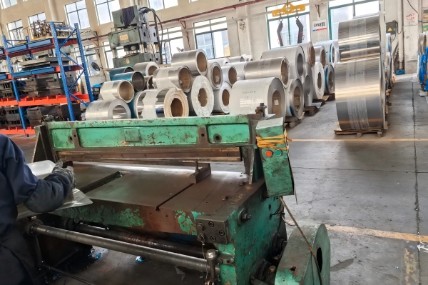
In the entire sheet metal manufacturing process, shearing and blanking represent the most fundamental and widely applied primary cutting operations. These processes serve as the initial step in transforming raw coil or sheet metal into usable blanks, which are then further processed by bending, punching, laser cutting, stamping, welding, or assembly. As visualised in typical technical diagrams of shearing mechanisms, the entire procedure relies on the relative movement of an upper blade and a lower blade to exert sufficient force, inducing plastic deformation and final fracture along a predetermined line.
MetalFabricationChina is a professional Sheet metal fabrication manufacturer in China with fully equipped hydraulic shearing machines, CNC-controlled feeding systems, precision positioning devices, and systematic quality inspection procedures. By strictly controlling blade clearance, cutting angles, hold-down pressure, and back-gauge positioning, we ensure that every sheared or blanked part meets dimensional accuracy, edge quality, and flatness requirements for industries such as construction, automotive components, electrical enclosures, machinery parts, and custom metal fabrication. This article provides an in-depth analysis of shearing and blanking based on actual process principles, deformation behaviour, machine structure, key process parameters, common defects, and quality control methods.
1. Basic Concepts of Shearing and Blanking
Shearing and blanking are both classified as mechanical sheet cutting processes, but they serve slightly different purposes in production.
Shearing generally refers to cutting along a straight line to separate a large sheet into smaller sheets, strips, or desired lengths. It is typically used for blank preparation, edge trimming, and linear cutting of medium to thick sheets.
Blanking refers to cutting a closed contour to separate a part from the surrounding material, resulting in a finished or semi-finished piece. In many practical production scenarios, the two processes share similar mechanical principles, tooling structures, and deformation mechanisms.
Both processes share the following characteristics:
- High production efficiency suitable for mass manufacturing
- No chip formation during cutting
- Relatively low cost compared to thermal cutting methods
- Dependence on blade sharpness and clearance for surface quality
- Applicable to steel, stainless steel, aluminum, copper, and other sheet materials
At the core of both processes is the interaction between the rigid blades and the sheet metal, leading to a predictable sequence of compression, penetration, plastic flow, and fracture.
2. Shearing Deformation Zones (Based on Cross-Section Diagram)
As clearly illustrated in shear cross-section diagrams, when the upper blade moves downward and presses into the sheet metal, four distinct zones form along the cutting edge. Understanding these zones is essential for optimizing process parameters and improving part quality.
2.1 Roll-Over Zone
The roll-over zone appears at the top surface of the sheet, directly under the upper blade. As the blade first makes contact, it exerts vertical pressure that causes plastic flow on the surface layer. This creates a slightly rounded or depressed edge. The width and depth of this zone are affected by blade sharpness, cutting speed, and material hardness.
2.2 Burnish Zone
Beneath the roll-over zone lies the burnish zone, which is smooth, bright, and perpendicular to the sheet surface. This zone is formed when the blade penetrates the material and creates a clean, sheared surface. A larger and more uniform burnish zone indicates ideal shearing conditions, proper clearance, and sharp blades.
2.3 Fracture Zone
Below the burnish zone is the fracture zone, which appears rough, granular, and uneven. When the internal stress of the material exceeds its tensile strength, the metal fractures naturally rather than being continuously cut. The inclination and roughness of this zone are directly related to blade clearance and material ductility.
2.4 Burr Zone
The burr zone forms at the bottom edge of the sheet, near the lower blade. It consists of a thin, raised, sharp edge caused by the final tearing of the material. Excessive burrs affect dimensional accuracy, assembly performance, and subsequent welding or bending operations.
In high-quality shearing, the goal is to maximize the burnish zone, minimize the fracture zone, and control burr height within acceptable limits.
3. Structure of Shearing Machine (Based on Mechanical Structure Diagram)
The shearing machine’s structure directly determines cutting stability, dimensional accuracy, and operational safety. Key components shown in structural diagrams include:
3.1 Upper Blade and Lower Blade
The upper blade moves downward to perform cutting, while the lower blade remains fixed on the worktable. Both blades are made of high-strength alloy tool steel with high hardness and wear resistance. The parallelism between the two blades directly affects cutting straightness and edge uniformity.
3.2 Hold-Down Pad (Clamping Device)
The hold-down pad presses the sheet firmly against the worktable before cutting begins. This prevents lifting, shifting, or warping during shearing. Insufficient pressure leads to inaccurate dimensions and distorted edges.
3.3 Back Gauge System
The back gauge is a precision positioning component that sets the cutting length. CNC-controlled back gauges allow automatic positioning and repeated accuracy, essential for batch production.
3.4 Frame, Guide Rails, and Sliding Mechanism
The rigid frame absorbs cutting force and reduces vibration. Precise guide rails ensure the upper blade moves vertically without deviation, maintaining straight cuts.
3.5 Hydraulic or Mechanical Drive System
Modern shearing machines mostly use hydraulic drive for stable force, low noise, and adjustable pressure. The drive system controls stroke, speed, and pressure to adapt to different sheet thicknesses.
3.6 Protective Devices and Safety Mechanisms
These include safety guards, emergency stop buttons, and optical sensors to protect operators during high-speed cutting.
4. Key Process Parameters in Shearing and Blanking
Based on technical parameter diagrams, the following parameters determine cutting quality and must be precisely adjusted.
4.1 Blade Clearance
Blade clearance is the horizontal gap between the upper and lower blades.
- Typical value: 2% to 7% of sheet thickness
- Too small clearance: increases cutting force, causes double fracture, shortens blade life
- Too large clearance: produces large burrs, increases fracture roughness, reduces dimensional accuracy
- Clearance varies by material: softer materials require smaller clearance; harder materials require slightly larger clearance
4.2 Blade Inclination Angle
The upper blade is usually inclined at a small angle to reduce instantaneous cutting force.
- Standard angle: 2° to 6°
- Larger angle reduces force but may increase material deformation
- Smaller angle provides straighter cuts but requires higher machine capacity
4.3 Cutting Edge Angle
The cutting edge angle affects penetration efficiency.
- For steel sheets: 75° to 85°
- For aluminum and soft alloys: 65° to 75°
- Correct angle reduces wear and improves surface quality
4.4 Hold-Down Pressure
Hold-down pressure must be sufficient to fix the sheet without causing indentations.
- Thin sheets require lower pressure
- Thick or slippery materials require higher pressure
- Uneven pressure leads to skewed cuts and dimensional errors
4.5 Cutting Speed
Moderate cutting speed improves edge quality.
- Excessively high speed increases vibration and burrs
- Low speed improves precision but reduces efficiency
5. Complete Shearing & Blanking Process Flow

Based on process flow diagrams, the entire operation follows a strict sequence to ensure stability.
Step 1: Material Preparation
- Check material type, thickness, and surface condition
- Remove oil, rust, dust, and deformation
- Confirm sheet flatness to avoid positioning errors
Step 2: Machine Calibration
- Adjust blade clearance according to thickness
- Set blade angle and stroke
- Calibrate back gauge to target dimensions
- Test hold-down pressure
Step 3: Sheet Positioning
- Place sheet against the back gauge and side guide
- Ensure no gap between sheet and positioning stops
- Activate clamping to secure the workpiece
Step 4: Cutting Execution
- Initiate cutting cycle
- Upper blade descends steadily to complete shearing
- Avoid multiple strokes on the same cutting line
Step 5: Preliminary Inspection
- Check length, width, squareness, and parallelism
- Inspect edge quality for excessive burrs or cracks
- Verify flatness and absence of warping
Step 6: Deburring and Finishing
- Remove burrs using files, brushes, or deburring machines
- Smooth sharp edges for safe handling and downstream processing
- Prepare parts for bending, welding, or powder coating
Step 7: Final Quality Control and Packaging
- Conduct full-dimensional inspection
- Sort qualified parts
- Protect surfaces from scratches during packaging
6. Common Defects, Causes and Solutions (Based on Defect Analysis Charts)
Many quality issues in shearing can be traced directly to incorrect parameters or machine conditions.
6.1 Excessive Burrs
Causes:
- Dull or worn cutting edges
- Excessive blade clearance
- Insufficient hold-down pressure
- Incorrect cutting angle
Solutions:
- Sharpen or replace blades
- Readjust clearance to standard range
- Increase clamping force
- Recalibrate blade angle
6.2 Dimensional Inaccuracy
Causes:
- Back gauge misalignment
- Sheet movement during cutting
- Worn guide rails
- Improper feeding
Solutions:
- Recalibrate positioning system
- Strengthen hold-down pressure
- Replace or repair guide components
- Standardize operating procedures
6.3 Crooked or Skewed Cutting Edges
Causes:
- Blades not parallel
- Uneven hold-down pressure
- Sheet placed at an angle
- Machine frame deformation
Solutions:
- Adjust blade parallelism
- Balance pressure across the sheet
- Use side guides for alignment
- Perform machine maintenance
6.4 Sheet Warping or Bending
Causes:
- Insufficient clamping
- Vibration during cutting
- Thin sheet flexibility
- Uneven blade pressure
Solutions:
- Use full-length hold-down pads
- Reduce cutting speed
- Add auxiliary supports
- Optimize blade parallelism
6.5 Surface Scratches or Indentations
Causes:
- Rough worktable surface
- Hard particles under the sheet
- Excessive hold-down pressure
- Sharp edges on fixtures
Solutions:
- Clean table surface
- Use protective plastic or leather pads
- Reduce clamping pressure appropriately
- Polish contact surfaces
7. Quality Control Standards at MetalFabricationChina
As a professional manufacturer, MetalFabricationChina is a professional Sheet metal fabrication manufacturer in China and implements strict quality control throughout shearing and blanking processes.
7.1 Dimensional Tolerance Control
- Standard tolerance: ±0.1 mm to ±0.5 mm based on sheet size and thickness
- CNC back gauges ensure repeatability in mass production
- Regular calibration of measuring tools such as calipers, squares, and gauges
7.2 Edge Quality Evaluation
- Control burr height below 0.1 mm for precision parts
- Ensure a consistent and sufficient burnish zone
- Avoid cracks, notches, or work-hardened layers that affect formability
7.3 Flatness Control
- Limit warping and bowing after shearing
- Use leveling devices when necessary
- Ensure parts meet assembly requirements without manual correction
7.4 Equipment Maintenance System
- Daily inspection of blade condition
- Weekly calibration of clearance and positioning
- Monthly maintenance of hydraulic systems and guide rails
- Timely replacement of worn parts to ensure stability
8. Application Industries of Sheared & Blanked Parts
Shearing and blanking provide essential blanks for a wide range of industries:
- Construction: steel brackets, frames, panels, supports
- Automotive: structural parts, chassis components, covers
- Electrical & Electronic: enclosures, cabinets, mounting plates
- HVAC: duct sections, flanges, connectors
- Machinery: base plates, covers, structural components
- Custom metal fabrication: tailored parts according to client drawings
With high efficiency and reliability, shearing remains irreplaceable in modern sheet metal factories, especially for large-scale linear cutting and blank preparation.
9. Conclusion
Shearing and blanking are core processes in sheet metal fabrication, and their quality directly influences the accuracy and performance of finished products. By fully understanding the four deformation zones, optimizing blade clearance and angle settings, maintaining proper machine structure, and implementing systematic defect control, manufacturers can achieve stable, high-quality cutting results.
At MetalFabricationChina, we combine advanced machinery, professional technical teams, and strict quality management systems to provide reliable shearing and blanking services for global customers. Whether for simple linear cutting or complex blanking parts, we ensure consistency, precision, and cost-effectiveness for projects of all scales.
MetalFabricationChina is a professional Sheet metal fabrication manufacturer in China committed to delivering superior sheet metal solutions through technical expertise and standardized production.


