
Sheet Metal Layout and Cutting: A Comprehensive Guide
December 30, 2025
Sheet Metal Design Tips to Lower Cost
March 10, 2026Key Factors Affecting Blank Cutting of Sheet Metal Parts
Abstract
 In modern precision manufacturing, sheet metal blank cutting (also referred to as sheet metal nesting, blanking, or rough cutting) stands as the foundational and cost-critical first step in the entire sheet metal fabrication workflow. The quality, efficiency, material utilization rate, and dimensional accuracy of blank cutting directly determine downstream processing efficiency, final product performance, production cost control, and overall enterprise profitability. Even minor oversights in blank cutting planning or parameter setting can lead to massive material waste, repeated rework, delayed delivery schedules, and compromised part structural integrity. This comprehensive, in-depth article systematically dissects all core factors influencing sheet metal blank cutting, covering material inherent properties, part geometric design, processing equipment parameters, process flow control, nesting optimization strategies, and post-cutting deformation control. Combined with multiple real-world industrial production cases paired with visual reference graphics, it provides actionable, data-backed guidance for sheet metal manufacturers to optimize blank cutting operations. MetalFabricationChina is a professional metal fabrication and plastic molding manufacturer in China, with years of frontline production experience in sheet metal blanking, nesting, and full-process precision fabrication, and has successfully resolved hundreds of complex blank cutting challenges for global clients across construction, machinery, electronics, automotive, and HVAC industries. This article integrates the manufacturer’s practical technical accumulation and industry best practices to deliver a fully actionable, SEO-aligned guide for sheet metal production engineers, process designers, and manufacturing managers worldwide.
1. Introduction to Sheet Metal Blank Cutting in Modern Manufacturing
Sheet metal blank cutting is defined as the process of cutting raw sheet metal coils or flat sheets into pre-designed blank shapes and sizes that match the final part requirements, through mechanical shearing, laser cutting, plasma cutting, waterjet cutting, or stamping blanking. Unlike simple material cutting, modern sheet metal blank cutting is a highly systematic engineering task that integrates material science, mechanical engineering, computer-aided design (CAD), computer-aided manufacturing (CAM), and production management. It is no longer a purely mechanical operation but a strategic link that balances precision, efficiency, cost, and sustainability.
For global manufacturing enterprises, especially those engaged in mass production or custom precision sheet metal fabrication, blank cutting optimization can generate direct and measurable economic benefits. Industry statistics show that for most sheet metal products, raw material costs account for 60%-75% of total production costs, and blank cutting material waste is one of the largest controllable cost drivers. A 5% improvement in material utilization rate can reduce overall production costs by 3%-8% for most sheet metal parts, while also shortening production cycles and reducing carbon emissions associated with material production and waste disposal. In the context of increasingly fierce global manufacturing competition, rising raw material prices, and stricter environmental regulations, mastering the key factors affecting sheet metal blank cutting and implementing targeted optimization has become a core competitive advantage for sheet metal fabrication enterprises.
Common sheet metal blank cutting processes include manual shearing, CNC shearing, fiber laser cutting, plasma cutting, waterjet cutting, mechanical stamping blanking, and combined processing. Each process has its own applicable scenarios, advantages, and limitations, and the selection of the cutting process itself is a critical factor affecting blank cutting quality and efficiency. Additionally, factors such as sheet material type, thickness, ductility, surface coating, part geometry complexity, corner radii, bending requirements, welding deformation, machining allowances, and nesting algorithms all interact to jointly determine the final effect of blank cutting. This article will analyze each factor in detail and verify its impact through real production cases with supporting visuals, providing a full-cycle reference for sheet metal blank cutting optimization.
2. Material Properties: The Most Fundamental Factor Affecting Sheet Metal Blank Cutting
Material properties are the inherent basis of sheet metal blank cutting, and all cutting parameters, tool selection, and nesting strategies must be formulated around the specific characteristics of the sheet material. Ignoring material properties will inevitably lead to cutting defects, dimensional deviations, material cracking, or excessive tool wear. The core material properties affecting blank cutting include thickness, mechanical properties (ductility, tensile strength, yield strength), anisotropy, surface state, and coating characteristics. Each property has a distinct and non-negligible impact on the blank cutting process.
2.1 Sheet Thickness and Stiffness
Sheet thickness is the most intuitive and basic factor affecting blank cutting. Thickness directly determines cutting force requirements, cutting tool selection, cutting clearance, processing speed, and deformation risk. Generally, thin sheets (below 1.5mm) have low stiffness and are prone to warping, vibration, and tearing during cutting; medium-thickness sheets (1.5mm-6mm) are the most widely used in general sheet metal fabrication, with balanced processability; thick sheets (above 6mm) require higher cutting power, larger tool clearance, and slower processing speed, and are more prone to thermal deformation during thermal cutting processes (laser, plasma).
For sheets with a thickness ≥1.5mm, especially those with inclined cross-sections, dimensional control during blank cutting becomes more difficult, and stress concentration is prone to occur at the cutting edge, which affects subsequent bending and welding processes. In actual production, the thickness tolerance of raw sheets must also be considered. Raw sheets with uneven thickness will cause inconsistent cutting effects, even if the cutting parameters are fixed. For example, a sheet with a nominal thickness of 3mm but a local thickness deviation of ±0.2mm may lead to burrs on one side and incomplete cutting on the other during CNC shearing, requiring secondary trimming and increasing production costs.
Real Production Case 1: Carbon Steel Sheet Thickness Matching Blank Cutting Optimization (MetalFabricationChina Client Project)
Project Background: A European industrial equipment client commissioned MetalFabricationChina to produce 50,000 sets of equipment support brackets, using Q235 carbon steel sheets, with two thickness specifications: 2mm and 5mm. The initial blank cutting plan adopted unified laser cutting parameters and conventional nesting, resulting in two core problems: 2mm thin sheets suffered severe warping after laser cutting, with a flatness deviation exceeding 1.2mm, which could not meet subsequent bending and assembly requirements; 5mm thick sheets had slow cutting speed, large thermal deformation at the cutting edge, and a burr height exceeding 0.3mm, requiring manual deburring, with a material utilization rate of only 78%.
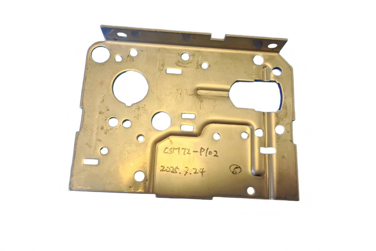
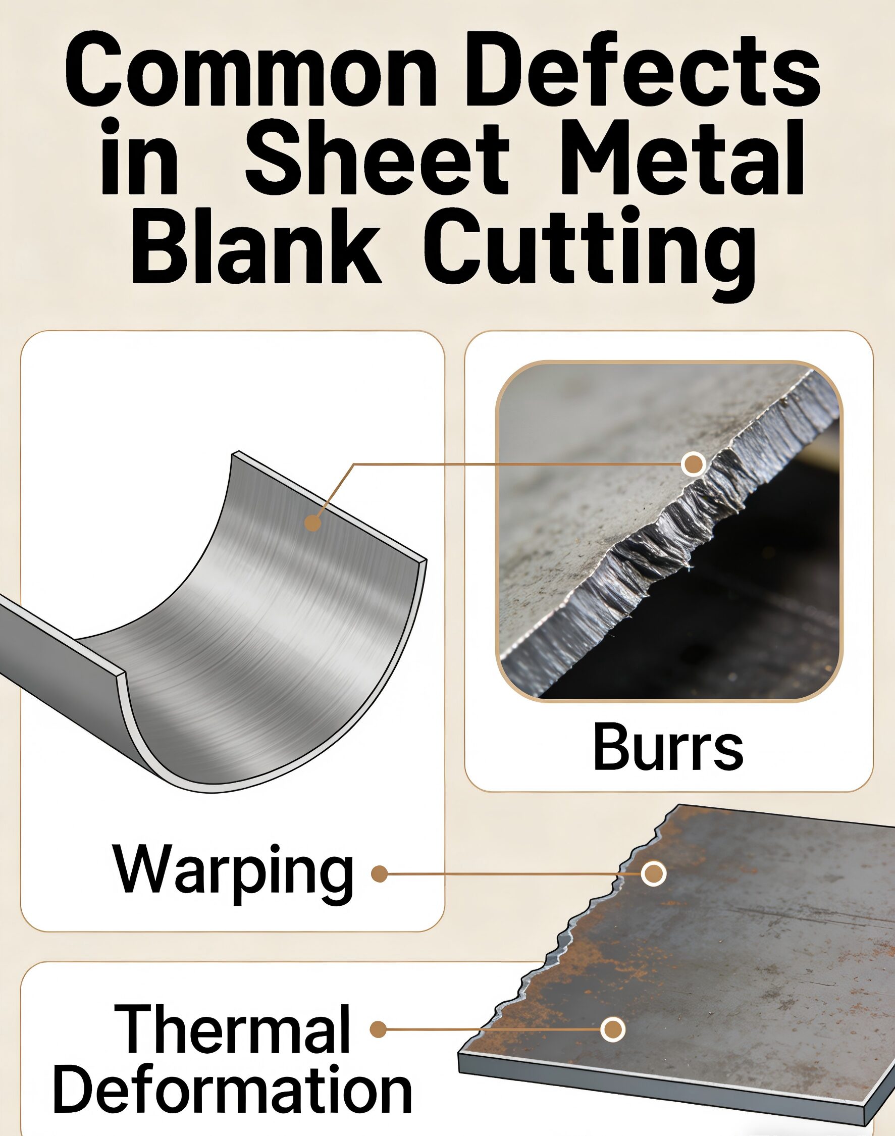 Figure 1: Original Blank Cutting Defects – Thin Sheet Warping & Thick Sheet Burr Formation
Problem Analysis: The core issue was mismatched cutting parameters and material thickness. 2mm Q235 steel has low stiffness, and high-power laser cutting with fast speed caused thermal stress concentration and warping; 5mm thick steel required higher laser power and adjusted auxiliary gas pressure, and conventional nesting did not consider thick sheet cutting edge reserved margins, leading to excessive burrs and material waste.
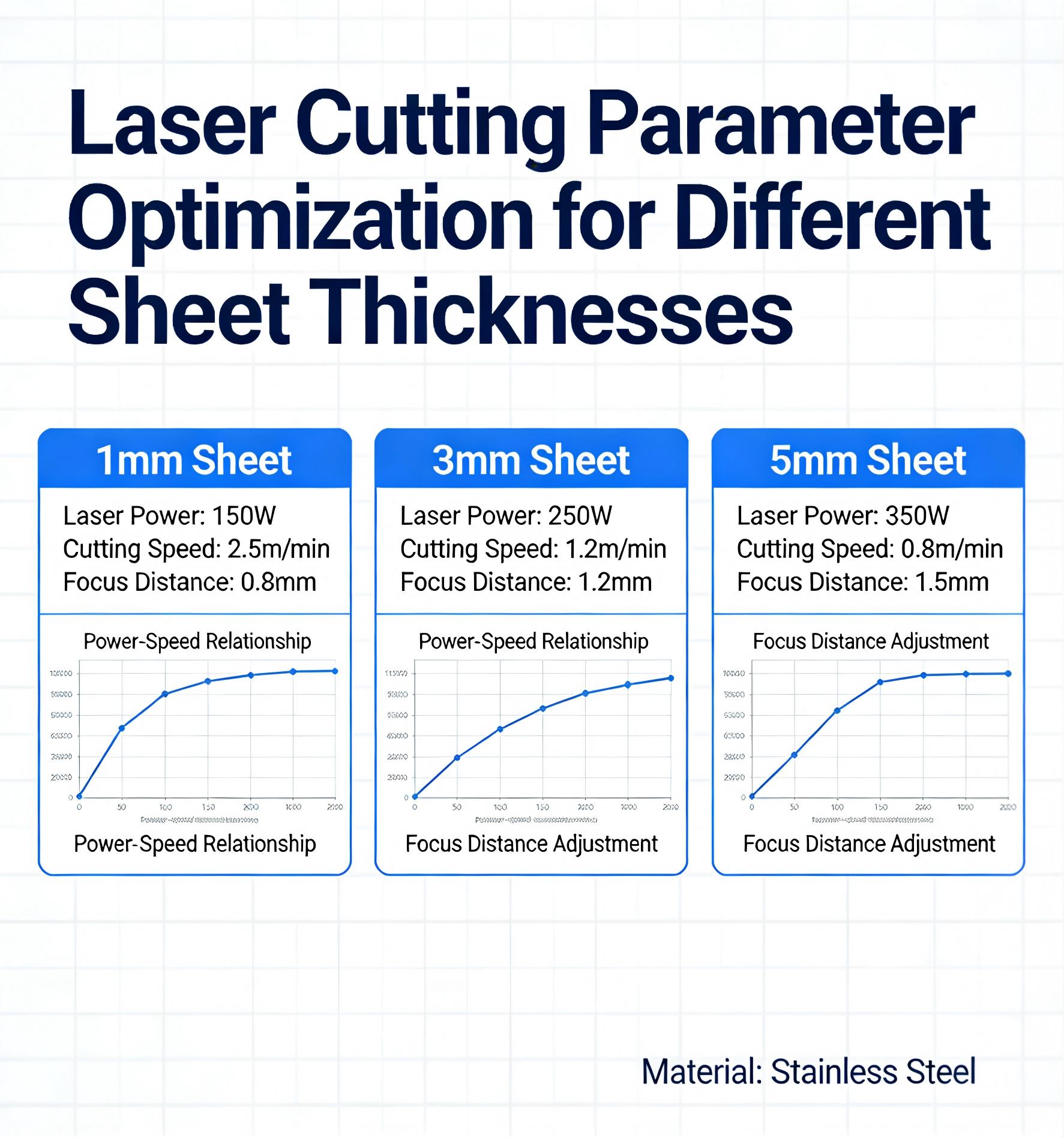
Figure 2: Laser Cutting Parameter Adjustment for Different Sheet Thicknesses
Optimization Plan Implemented by MetalFabricationChina: 1. For 2mm thin sheets, reduce laser power by 30%, reduce cutting speed by 20%, add micro-connections (0.3mm width) during nesting to fix the blank and prevent warping, and adopt dense nesting with small spacing to improve material utilization; 2. For 5mm thick sheets, increase laser power by 25%, adjust oxygen auxiliary gas pressure to 0.8MPa, increase cutting clearance by 0.2mm, optimize nesting layout to leave uniform cutting margins around the blank, and avoid dense arrangement of multiple blanks to reduce thermal superposition deformation; 3. Classify raw materials by actual thickness before cutting, and group sheets with thickness deviations within ±0.1mm for unified processing.
 Figure 3: Optimized Nesting Layout for Thin & Thick Carbon Steel Blanks
Final Results: After optimization, the flatness deviation of 2mm thin sheet blanks was controlled within 0.3mm, meeting direct subsequent processing requirements; the burr height of 5mm thick sheet blanks was reduced to below 0.1mm, eliminating manual deburring processes; material utilization rate increased from 78% to 89%, saving 11% of raw material costs, and production efficiency increased by 28%, successfully completing the order on schedule with zero quality complaints. This case fully proves that sheet thickness is a core factor that must be prioritized in blank cutting, and targeted parameter adjustment can fundamentally resolve quality and cost issues.
2.2 Material Ductility, Tensile Strength and Formability
Material ductility and tensile strength directly affect cutting formability, edge quality, and deformation risk. Materials with high ductility (such as low-carbon steel, 304 stainless steel, 1060 aluminum alloy) have good plasticity, are not prone to cracking during cutting, but are more likely to produce burrs and sticky slag during thermal cutting; materials with high tensile strength and low ductility (such as high-strength steel, spring steel, cast aluminum alloy) are hard and brittle, prone to edge cracking, chipping, and tool wear during mechanical cutting, and require special cutting parameters and tooling.
For sheet metal parts requiring subsequent bending, flanging, or deep drawing, ductility is a key indicator. If the material ductility is insufficient, the blank may crack at the bending position during subsequent forming, even if the blank cutting size is accurate. Therefore, in the blank cutting stage, the forming performance of the material must be fully considered, and the blank size should be reserved with corresponding forming allowances to avoid scrap caused by subsequent forming failure. Additionally, material hardness affects tool life: high-hardness sheets accelerate the wear of shearing blades and stamping dies, increasing the frequency of tool sharpening and replacement, which in turn affects blank cutting dimensional stability.
2.3 Material Anisotropy and Rolling Direction
Most industrial sheet metals are formed by rolling, resulting in obvious anisotropy of mechanical properties—mechanical properties such as tensile strength, ductility, and bending performance vary along the rolling direction and transverse direction. This anisotropy has a crucial impact on blank cutting and subsequent forming, especially for bending parts. If the bending direction is parallel to the rolling direction, the material is prone to cracking at the bending fillet; if perpendicular to the rolling direction, the bending performance is significantly improved.
In actual blank cutting and nesting, the rolling direction of the sheet must be marked in advance, and the blank layout should be adjusted according to the part’s bending direction. For welded sheet metal parts, the weld seam direction should be perpendicular to the rolling direction to avoid weld cracking or deformation caused by material anisotropy. For example, duplex stainless steels and high-strength steel sheets have more significant anisotropy, and nesting without considering the rolling direction will lead to a 30% higher scrap rate in subsequent bending processes.
2.4 Surface Coating and Surface State
Surface-coated sheets (galvanized sheets, aluminized sheets, painted sheets, passivated sheets) are widely used in outdoor, anti-corrosion, and electronic equipment industries. The coating characteristics directly affect blank cutting quality: hard and brittle coatings are prone to peeling, cracking, and falling off during mechanical shearing or stamping; organic coatings are prone to thermal melting and sticking during laser or plasma cutting, contaminating the cutting edge and affecting subsequent welding and assembly.
For coated sheets, the blank cutting process selection is more stringent. Generally, fiber laser cutting with low thermal influence is preferred to reduce coating thermal damage; mechanical shearing requires sharp blades and appropriate clearance to avoid coating peeling. In addition, sheets with surface scratches, rust, or unevenness will cause cutting deviation and edge defects, so raw material surface inspection is a necessary pre-process before blank cutting.
3. Part Geometric Factors: Core Determinants of Blank Cutting Difficulty and Material Utilization
Part geometric design is a man-made factor that directly determines the difficulty of blank cutting, nesting efficiency, and material utilization rate. A reasonable geometric design can reduce blank cutting difficulty by 50% and improve material utilization rate by more than 15%, while an unreasonable geometric design will lead to inevitable material waste and processing difficulties. Core geometric factors include part shape complexity, corner radii, bending allowances, hole position distribution, dimensional tolerances, and special structural design (such as conical, square-to-round, and special-shaped parts).
3.1 Part Shape Complexity and Regularity
Regular geometric shapes (rectangular, square, circular) are the easiest to nest and cut, with high material utilization rate and simple processing; irregular shapes (special-shaped curves, polygonal irregularities, complex cutouts) require advanced nesting software and precision cutting equipment, and are prone to material waste and cutting defects. In mass production, appropriately optimizing the part geometry (under the premise of meeting performance requirements) can significantly improve blank cutting efficiency.
Real Production Case 2: Irregular Square-to-Round Part Blank Cutting Optimization (Construction Machinery Industry)
Project Background: A domestic construction machinery manufacturer needed to produce 20,000 square-to-round transition parts for concrete mixer equipment, using 4mm Q355 high-strength steel. The original part geometry was an irregular expanded shape with sharp corners, and the initial manual nesting method had a material utilization rate of only 62%, with frequent dimensional deviations during cutting, and the scrap rate due to mismatched expanded size and subsequent forming reached 18%.
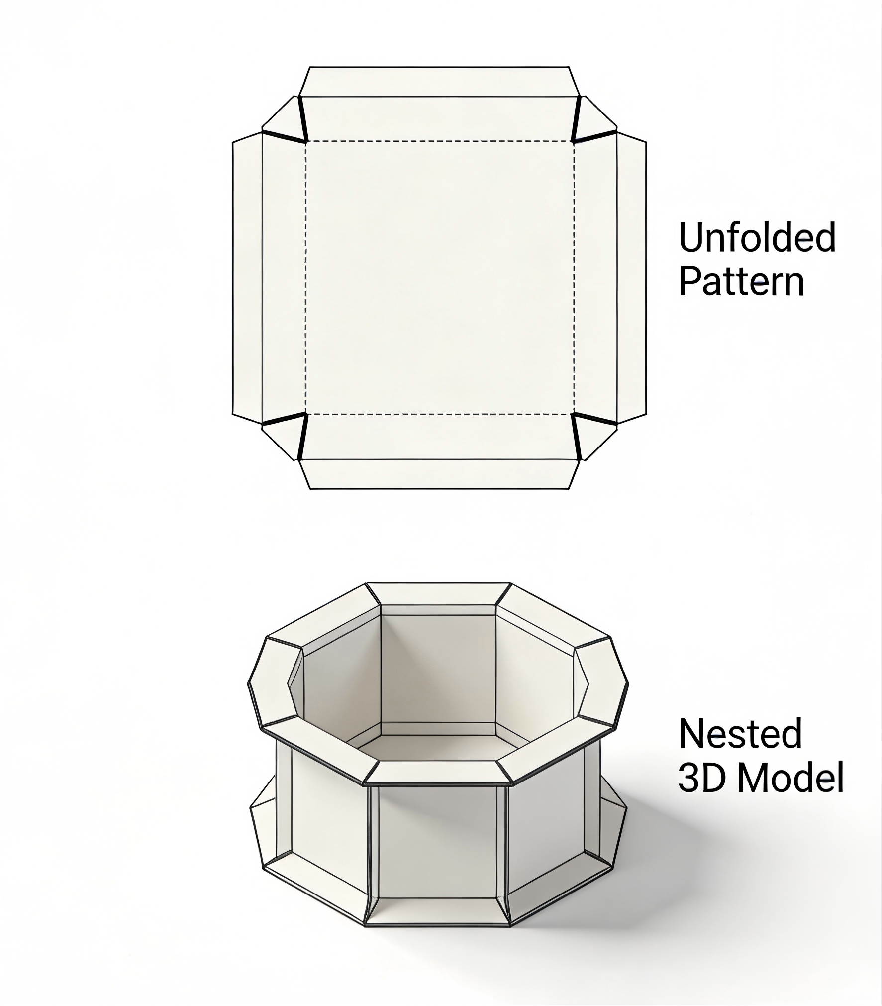 Figure 4: Square-to-Round Part Expanded Blank & Original Inefficient Nesting
Problem Analysis: The square-to-round part has an irregular expanded geometry, sharp corners causing stress concentration during cutting and forming, manual nesting could not achieve optimal layout, leaving a large number of irregular scrap edges, and the expanded size did not consider welding shrinkage allowances, leading to size mismatch after welding.
Optimization Plan: MetalFabricationChina’s engineering team first optimized the part geometry: rounded the sharp corners of the expanded blank to R8mm to reduce stress concentration and cutting burrs; calculated the accurate expanded size considering 0.5% welding shrinkage allowance; adopted professional CAD/CAM nesting software with genetic algorithm optimization, using half-blank nesting and mirroring layout to avoid excessive scrap; adjusted the blank orientation to ensure the rolling direction was perpendicular to the main bending line of the square-to-round part.
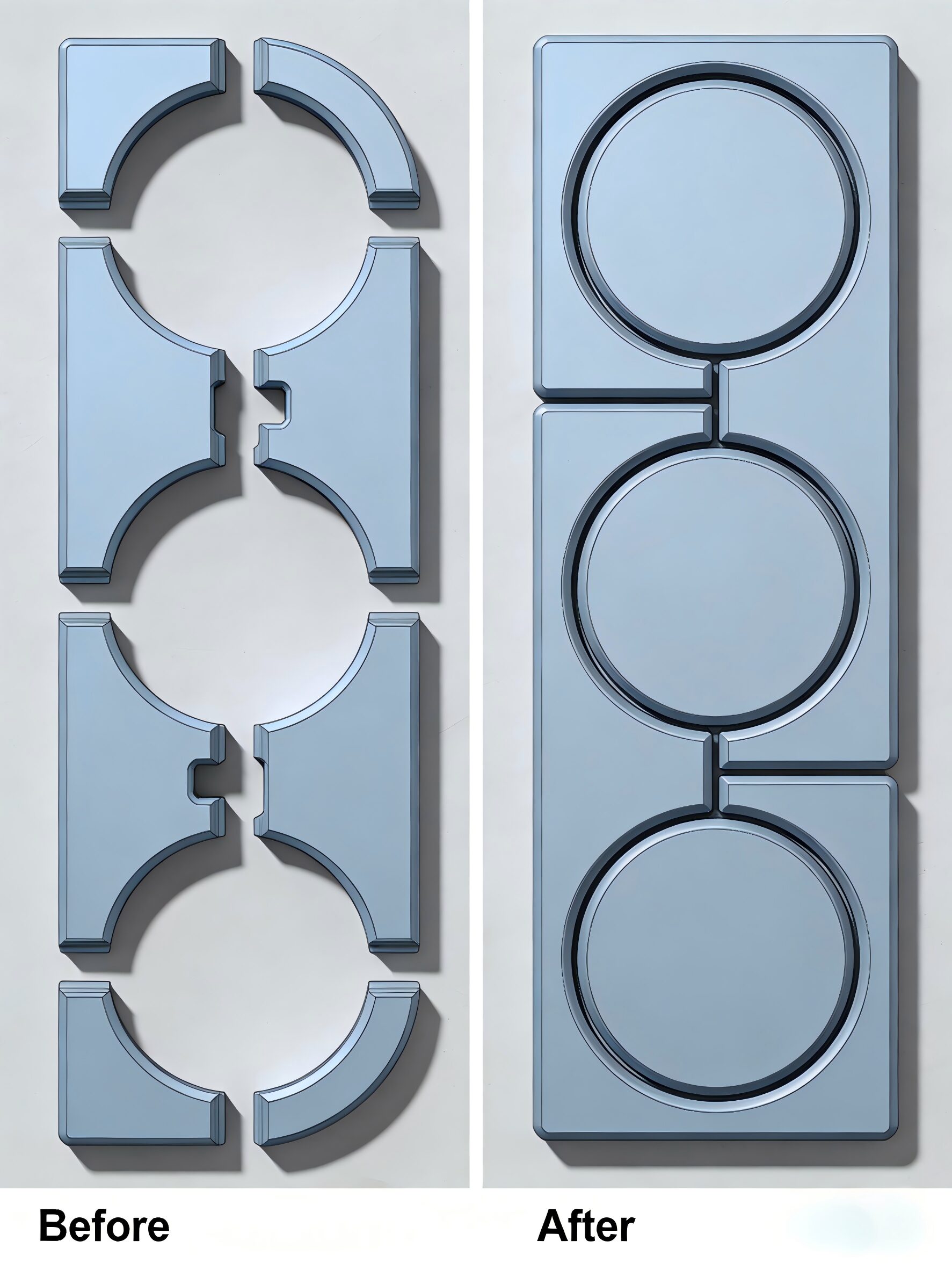
Figure 5: Nesting Effect Comparison – Before vs. After Optimization for Square-to-Round Blanks
Final Results: After geometric and nesting optimization, the material utilization rate of square-to-round parts increased from 62% to 81%, saving 19% of high-strength steel raw materials; the scrap rate due to dimensional deviation and forming failure dropped to 2.5%; cutting efficiency increased by 40%, and the subsequent welding and forming pass rate reached 99.2%. This case shows that for complex geometric parts, targeted geometric optimization and scientific nesting are the key to solving blank cutting problems.
3.2 Corner Radii, Bending Allowance and Neutral Axis Position
Corner radii and bending allowance are two closely linked geometric factors that directly affect the blank expanded size and cutting accuracy. When sheet metal is bent, the inner layer is compressed, the outer layer is stretched, and the neutral axis (no compression or tension) shifts toward the inner layer of the bend. The position of the neutral axis depends on the ratio of bending radius (r) to sheet thickness (δ): when r/δ ≤ 5.5, the neutral axis shifts significantly inward, and the bending allowance must be accurately calculated; when r/δ > 5.5, the neutral axis is close to the sheet center, and the bending allowance calculation is relatively simple.
Bending allowance calculation errors are the main cause of blank cutting dimensional deviation. Many manufacturers use empirical values instead of theoretical calculations, leading to the final part size being too long or too short after bending, resulting in scrap. In addition, the corner radius of the part cannot be too small: an overly small corner radius will cause cutting tool wear, material cracking, and stress concentration, and will also reduce material utilization rate. Appropriately increasing the corner radius (under the premise of meeting design requirements) can often reduce cutting difficulty and improve material utilization.
A typical example is the optimization of a rectangular oil tank blank: the original corner radius was R100mm, and after adjusting to R125mm, the arc length of the corner increased, but the straight edge length decreased more significantly, resulting in a net reduction of 43mm in the total blank length, reducing material consumption and improving the structural strength of the tank. This small geometric adjustment brings tangible cost savings, which is the value of scientific blank cutting design.
3.3 Dimensional Tolerances and Machining Allowances
The dimensional tolerance requirements of sheet metal parts directly determine the precision level of blank cutting. High-precision parts (tolerance ±0.1mm) require fiber laser cutting or precision stamping blanking, with strict control of cutting clearance and nesting accuracy; low-precision parts (tolerance ±0.5mm or above) can use CNC shearing or plasma cutting, with lower processing costs. In addition, machining allowances must be reserved for parts requiring subsequent milling, drilling, or grinding, considering the material removal amount and deformation caused by heat treatment and stress relief.
For example, an 8000mm long H-beam sheet metal part, after cutting and welding, will produce a camber of up to 8mm after single-side edge milling. If the blank cutting does not reserve this deformation allowance, the final machined part will be out of tolerance. Therefore, in the blank cutting stage, all subsequent processing deformations and machining allowances must be comprehensively considered to ensure the final part meets the tolerance requirements.
4. Processing Parameters and Equipment Factors: Directly Affecting Blank Cutting Quality and Efficiency
Processing parameters and equipment performance are the executive links of sheet metal blank cutting. Even with high-quality raw materials and reasonable geometric design, unreasonable parameters or outdated equipment will lead to poor cutting quality. Core equipment and process factors include cutting equipment type, cutting clearance, cutting speed, power (for thermal cutting), auxiliary gas, tool wear degree, and equipment precision.
4.1 Cutting Clearance Setting
Cutting clearance (the gap between the upper and lower blades for shearing, or between the punch and die for stamping, or the kerf width for laser cutting) is the most critical process parameter. Too small clearance will cause excessive tool wear, double shear, and rough cutting edge; too large clearance will cause material tearing, large burrs, and incomplete cutting. The optimal cutting clearance is related to material type, thickness, and hardness: generally, for low-carbon steel, the clearance is 5%-8% of sheet thickness; for stainless steel and aluminum alloy, it is 8%-12% of sheet thickness; for high-strength steel, it is 10%-15% of sheet thickness.
4.2 Thermal Cutting Parameters (Laser, Plasma)
For fiber laser cutting, the core parameters include laser power, cutting speed, auxiliary gas type (oxygen, nitrogen, compressed air), gas pressure, and focus position. Incorrect parameter matching will cause problems such as cutting non-penetration, burrs, thermal deformation, and coating damage. For example, cutting thin stainless steel sheets with nitrogen as auxiliary gas can obtain a smooth, oxide-free cutting edge; cutting thick carbon steel sheets with oxygen can improve cutting efficiency but requires controlling gas pressure to avoid excessive thermal deformation.
Real Production Case 3: High-Strength Steel (DP980) Laser Blank Cutting Optimization (Automotive Industry)
Project Background: An automotive parts manufacturer needed to produce automotive rocker panels using DP980 advanced high-strength steel (thickness 1.75mm), with high requirements for cutting edge quality and no edge cracking. The initial laser cutting parameters led to 22% of blanks with edge micro-cracks, which could not pass the automotive industry strength test, and the cutting speed was slow, failing to meet mass production delivery requirements.
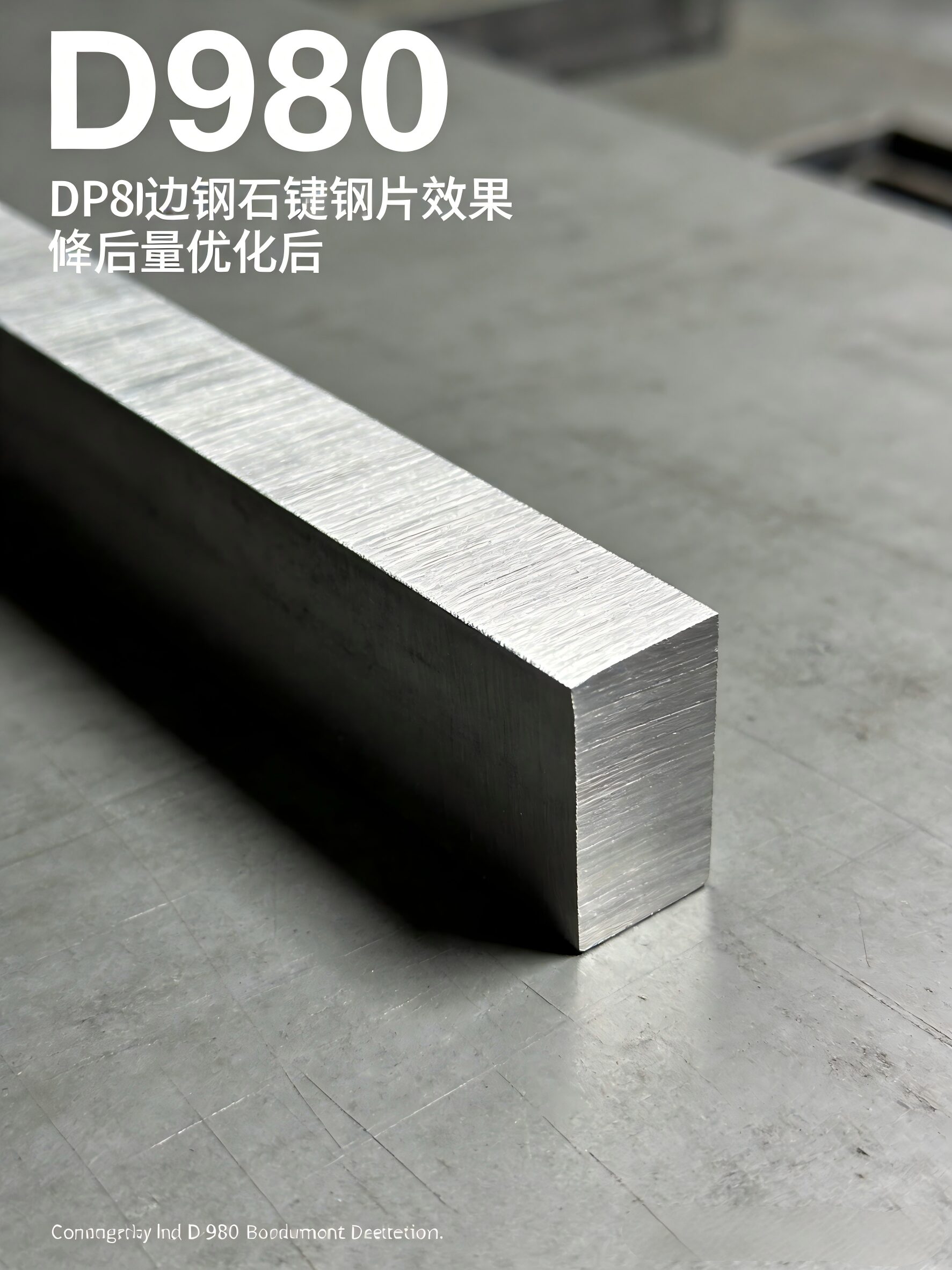 Figure 6: Edge Micro-Cracks in Unoptimized DP980 High-Strength Steel Blanks
Problem Analysis: DP980 high-strength steel has high hardness and low ductility, and conventional laser cutting parameters caused excessive thermal stress at the cutting edge, resulting in micro-cracks; the focus position was offset, leading to uneven cutting edge and stress concentration; the auxiliary gas pressure was insufficient, failing to remove molten metal in time, causing sticky slag and edge defects.
Optimization Plan: Adjust laser focus position to 0.2mm below the sheet surface; reduce cutting speed by 15% and increase laser power by 20% to ensure complete cutting; use high-purity nitrogen as auxiliary gas, increase gas pressure to 1.2MPa to quickly remove molten metal and reduce thermal influence; optimize nesting layout to increase the spacing between adjacent blanks to 15mm, avoiding thermal superposition and stress concentration; add a slight post-cutting cooling step to reduce residual stress.
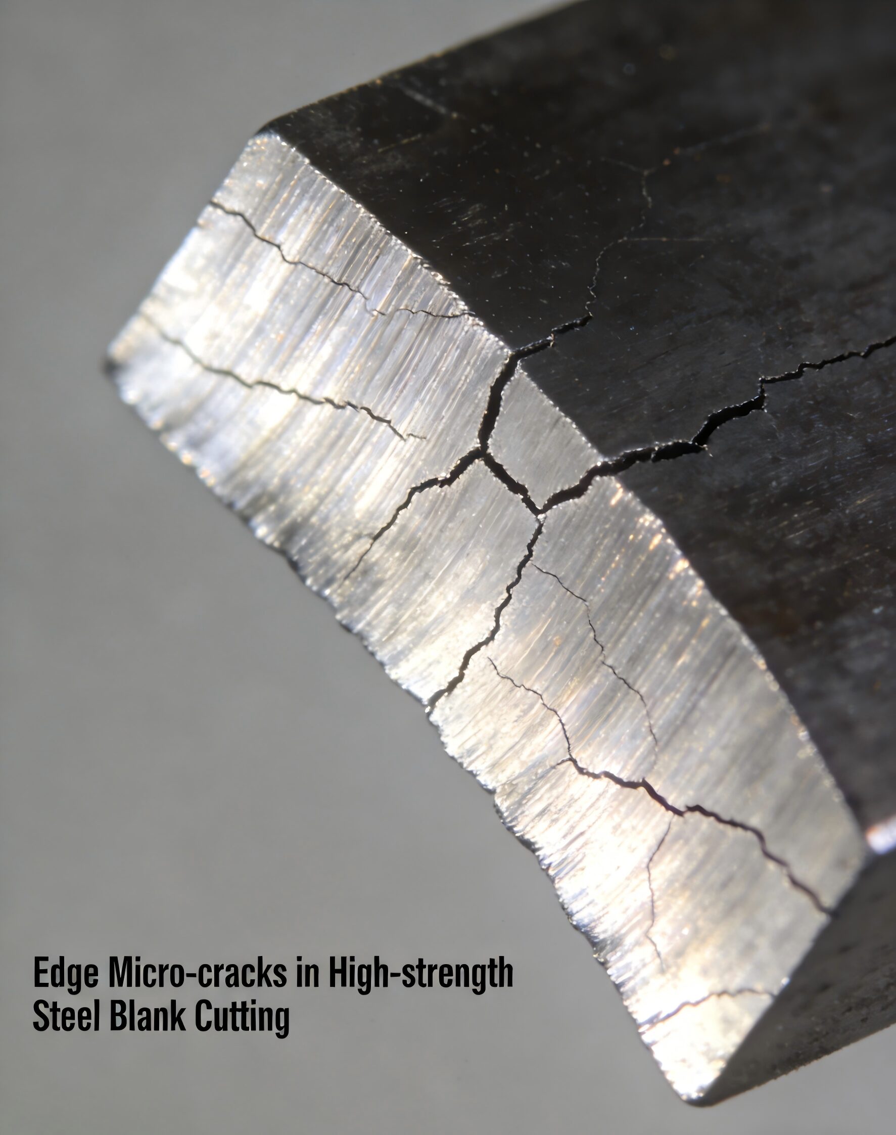 Figure 7: Optimized Crack-Free Cutting Edge of DP980 High-Strength Steel Blanks
Final Results: After parameter optimization, the edge micro-crack rate of DP980 high-strength steel blanks dropped to 1.2%, fully meeting automotive industry quality standards; cutting efficiency increased by 22%, and the cutting edge roughness was reduced by 60%, eliminating the need for secondary edge trimming. This case proves that precise adjustment of thermal cutting parameters is crucial for blank cutting of high-hardness, high-strength materials.
4.3 Equipment Precision and Tool Condition
The precision of blank cutting equipment (CNC shearing machine, laser cutting machine, stamping blanking machine) directly determines dimensional accuracy. Outdated equipment with poor positioning accuracy, large runout, or unstable transmission system will cause consistent dimensional deviations of blanks. Tool wear is also a key factor: worn shearing blades, laser nozzles, or stamping punches will produce burrs, rough edges, and dimensional errors, requiring regular tool inspection and replacement.
In addition, equipment automation level affects production efficiency: automated blank cutting lines with automatic loading, nesting, and unloading functions can reduce manual operation errors, improve cutting continuity, and increase daily output by more than 30% compared with manual operation equipment. MetalFabricationChina is a professional metal fabrication and plastic molding manufacturer in China, which is equipped with advanced CNC fiber laser cutting lines, automatic shearing equipment, and intelligent nesting systems, ensuring the stability and efficiency of blank cutting for various complex sheet metal parts.
5. Nesting Strategy and Operational Management Factors: The Key to Improving Material Utilization
Nesting strategy is the core link to improve sheet material utilization rate, which refers to the optimal arrangement of multiple part blanks on a single sheet to minimize scrap area. Scientific nesting can reduce material waste by 10%-30% compared with random or manual nesting, and is one of the most cost-effective optimization measures in sheet metal blank cutting. Core nesting factors include nesting sequence, raw sheet size selection, part orientation, scrap utilization, and batch nesting management.
5.1 Core Nesting Principles
The fundamental goal of nesting is to maximize the material utilization rate ψ = Zc / Zs (Zc: total mass of qualified blanks; Zs: total mass of raw sheets consumed). Industry-recognized core nesting principles include: 1. Large parts first, small parts later: nest large blanks first, then fill small blanks in the remaining gaps to reduce large-area scrap; 2. Close arrangement with uniform clearance: ensure the spacing between adjacent blanks meets cutting requirements, avoid excessive spacing waste; 3. Adapt to material characteristics: adjust blank orientation according to material rolling direction and anisotropy; 4. Utilize standard sheet sizes: select standard sheet specifications matching the total area of blanks to reduce edge scrap; 5. Multi-part mixed nesting: nest blanks of different parts in the same batch to improve overall utilization rate.
5.2 Intelligent Nesting Software vs. Manual Nesting
Traditional manual nesting relies on worker experience, with low efficiency and low material utilization rate, and is only suitable for small-batch, regular-shaped parts. Modern intelligent nesting software (based on genetic algorithm, simulated annealing algorithm, linear programming) can automatically calculate the optimal nesting layout within minutes, considering cutting kerf width, material rolling direction, and part orientation, and can achieve a material utilization rate 15%-25% higher than manual nesting. For mass production enterprises, investing in intelligent nesting software can recover costs within 3-6 months through material savings.
Real Production Case 4: HVAC Air Duct Sheet Metal Blank Cutting Nesting Optimization (Commercial Construction Industry)
Project Background: A commercial HVAC engineering company commissioned MetalFabricationChina to produce 120,000 pieces of rectangular galvanized air duct blanks (thickness 0.8mm), with a large number of standard rectangular blanks and matching small flange blanks. The original manual nesting method had a material utilization rate of only 72%, with a large amount of small scrap that could not be utilized, and the production cycle was tight, requiring a significant increase in efficiency and utilization rate.
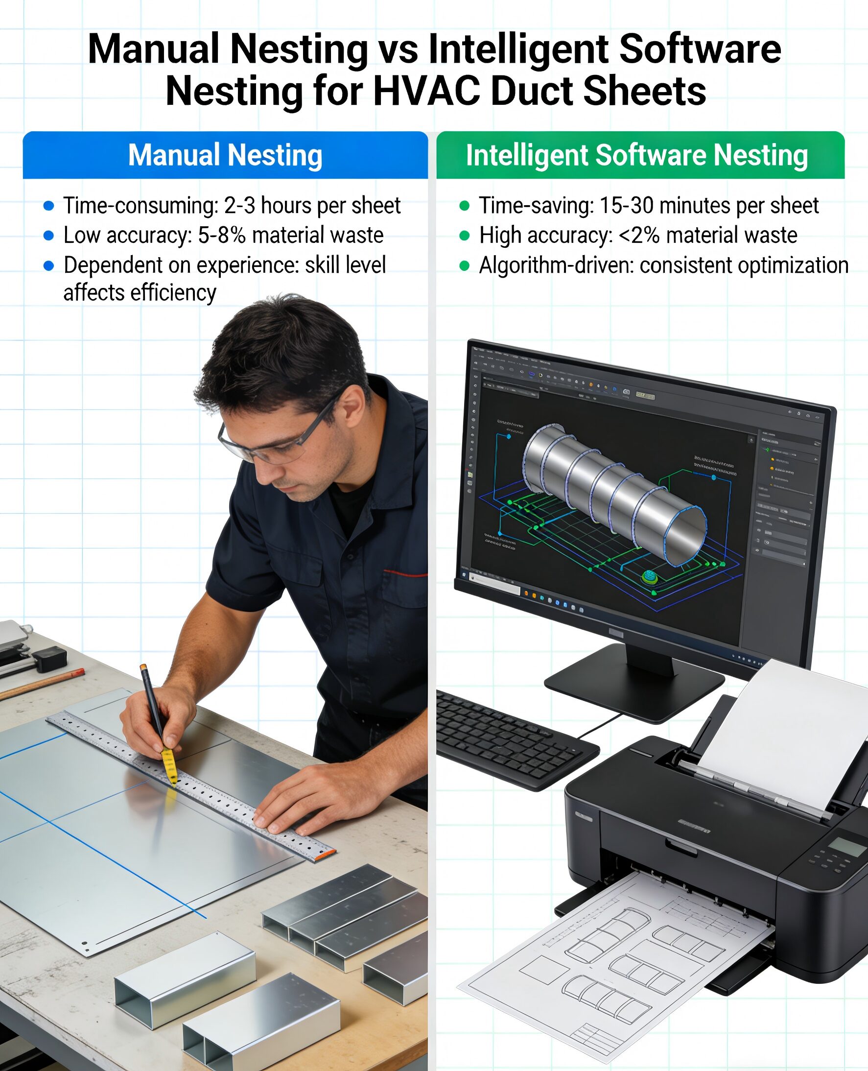 Figure 8: Manual Nesting vs. Intelligent Software Nesting for HVAC Duct Sheets
Problem Analysis: Manual nesting could not achieve mixed nesting of large and small blanks, resulting in a large number of edge scraps; the standard sheet size (1250mm×2500mm) was not fully matched with the blank size, leaving large edge margins; no consideration was given to galvanized coating protection during nesting, leading to partial coating peeling during cutting.
Optimization Plan: 1. Adopt professional sheet metal nesting software to realize mixed nesting of large air duct main body blanks and small flange blanks, filling small gaps with small blanks; 2. Adjust the raw sheet size to 1220mm×2440mm (international standard galvanized sheet size), which is more matched with the blank size, reducing edge scrap; 3. Set the cutting spacing to 1.2mm during nesting, add micro-connections to prevent thin sheet warping, and avoid cutting edges overlapping with sheet coating damaged areas; 4. Adopt batch nesting management, unified cutting of the same specification blanks to reduce equipment setup time.
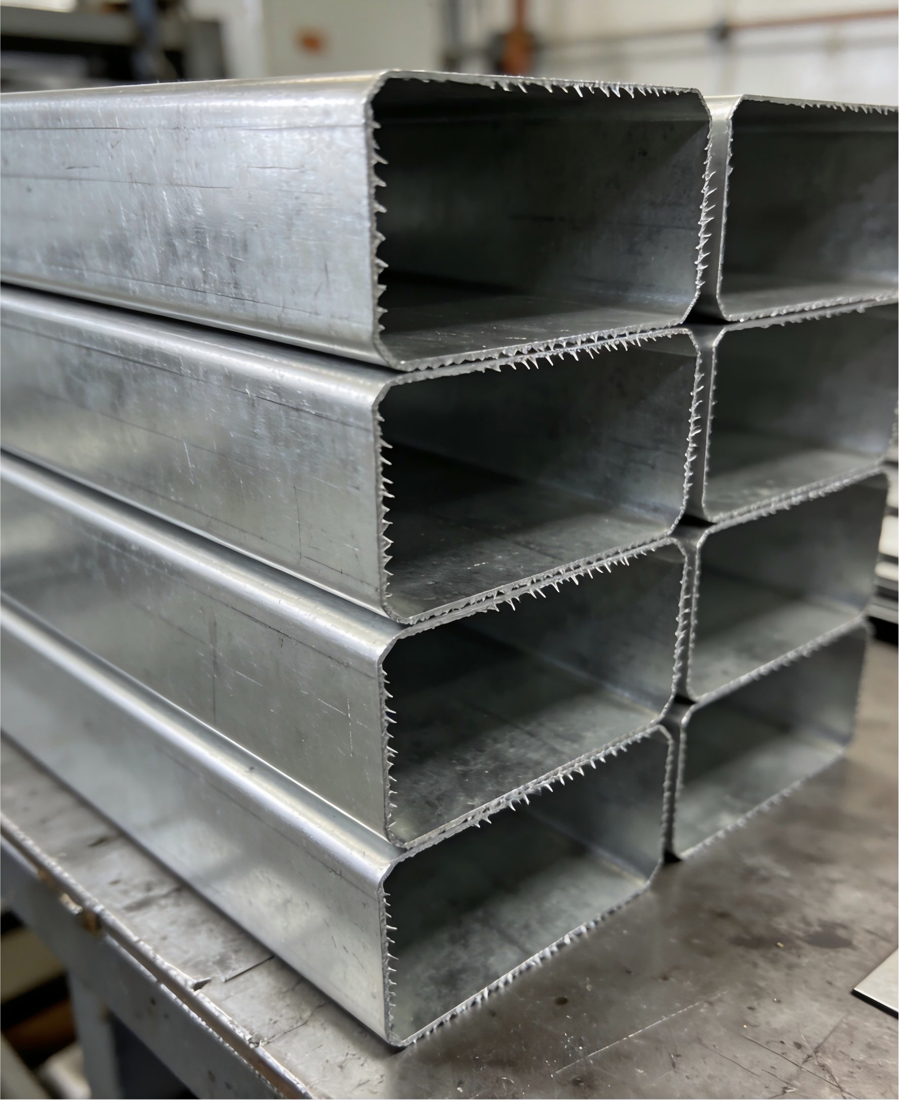 Figure 9: Finished HVAC Galvanized Air Duct Blanks with High Coating Integrity
Final Results: After nesting optimization, the material utilization rate of air duct blanks increased from 72% to 90%, saving 18% of galvanized sheet raw materials, equivalent to reducing 21.6 tons of sheet consumption for the entire order; production efficiency increased by 52%, and the coating integrity rate of blanks reached 98.5%, fully meeting the anti-corrosion requirements of HVAC air ducts. This case is a typical example of nesting strategy optimization bringing significant cost and efficiency benefits.
6. Post-Cutting Deformation and Quality Control Factors
Post-cutting deformation is a factor that is easily overlooked but has a significant impact on subsequent processing. Common post-cutting deformations include thermal deformation (warping, bending), mechanical deformation (collision, extrusion), and residual stress deformation. These deformations will cause blanks to fail to meet dimensional and flatness requirements, requiring subsequent straightening treatment, increasing production processes and costs.
Control measures for post-cutting deformation include: 1. For thermal cutting, adopt segmented cutting, micro-connection fixation, and reasonable cutting speed to reduce thermal stress; 2. For thin sheets, use special fixtures or support platforms during cutting to prevent vibration and warping; 3. Control the handling process after cutting, avoid collision and stacking extrusion; 4. For blanks with large residual stress, conduct stress relief treatment (natural aging, low-temperature tempering) before subsequent processing; 5. Strictly implement blank quality inspection (dimensional inspection, flatness inspection, burr inspection, coating inspection) to ensure unqualified blanks do not flow into the next process.
7. Comprehensive Optimization Path for Sheet Metal Blank Cutting
Based on the above analysis of various influencing factors and real production cases with visual references, the comprehensive optimization path for sheet metal blank cutting can be summarized as follows: 1. Raw material control: select sheets with stable quality, uniform thickness, and clear rolling direction, and conduct incoming inspection; 2. Design optimization: under the premise of meeting product performance, optimize part geometry, increase appropriate corner radii, simplify complex shapes, and accurately calculate bending and welding allowances; 3. Process selection: select the most suitable cutting process (laser, shearing, plasma) according to material thickness, precision requirements, and batch size; 4. Parameter calibration: set accurate cutting clearance, power, speed, and gas parameters according to material characteristics; 5. Intelligent nesting: use professional nesting software to maximize material utilization rate; 6. Equipment and tool management: regularly maintain equipment, replace worn tools, and ensure equipment precision; 7. Quality control: implement full-process inspection, control post-cutting deformation, and timely adjust processes according to quality feedback.
MetalFabricationChina is a professional metal fabrication and plastic molding manufacturer in China, which has established a full-process sheet metal blank cutting optimization system covering design, process, nesting, processing, and quality control. Relying on advanced equipment, professional technical teams, and years of practical experience, the manufacturer has provided high-quality, low-cost sheet metal blank cutting and fabrication services for more than 800 global clients, and can customize targeted blank cutting solutions for different materials, different shapes, and different batch parts, helping clients reduce costs and improve efficiency.
8. Conclusion
Sheet metal blank cutting is a complex systematic project affected by multiple interrelated factors, including material properties, geometric design, processing parameters, nesting strategy, equipment performance, and quality control. Each factor independently affects the cutting effect, and the interaction between factors further determines the final quality, cost, and efficiency of blank cutting. In the current manufacturing environment with rising raw material costs and increasingly fierce market competition, systematically analyzing and optimizing these key factors is not only a way to control production costs but also a core means to improve product quality and enterprise competitiveness.
The four real production cases in this article, paired with detailed visual graphics, cover the most common blank cutting scenarios in the industry: carbon steel thickness matching optimization, complex square-to-round part optimization, high-strength steel laser cutting optimization, and HVAC air duct nesting optimization. The optimization methods, data results, and visual comparisons have strong practical reference significance for sheet metal manufacturers of all scales. For enterprises, learning from these practical cases, applying scientific optimization concepts, and combining intelligent manufacturing technology can effectively improve material utilization rate, reduce production costs, improve product quality, and achieve sustainable development of sheet metal production.
In the future, with the development of intelligent manufacturing, Industry 4.0, and digital fabrication technology, sheet metal blank cutting will develop in the direction of higher automation, higher precision, and higher efficiency. Intelligent nesting systems integrated with big data, fully automated cutting production lines, and real-time quality monitoring technology will further reduce the impact of human factors and improve the stability and optimization level of blank cutting. Enterprises that actively embrace advanced technology and focus on process optimization will always occupy a dominant position in the global sheet metal fabrication market. MetalFabricationChina will continue to focus on sheet metal fabrication technology innovation, continuously optimize blank cutting processes, and provide more professional and efficient metal fabrication solutions for global clients.

