Working accuracy of bending machine
November 5, 2021
Water Proof Enclosure
November 11, 2021CNC punch processing countersink
What is countersink
The countersink described in this article is a process of chamfering the edge of the hole after punching a pre-punched hole on the plate. It is mainly used to sink the head of countersunk head screws or countersunk rivets, and guide tapping to avoid burrs.The countersink is widly to be used for sheet metal parts.
As a commonly used forming form on sheet metal parts, it can basically be processed and formed on a CNC punching machine, thereby reducing the operation mode of manual drilling machines.

Die structure for countersink processing
Dedicated interchangeable cutter head for single plate thickness
Currently the most commonly used recommendation type. The upper die can be quickly replaced with replaceable salad cutter heads. The thickness of the plate is special, which is easy to use and not easy to make mistakes.
It is suitable for the counterbore forming processing of most thick tower CNC punch presses. At the same time, due to the economical cost and convenient processing of the counterbore cutter head, it is especially suitable for sample processing and mass production of sheet metal products.
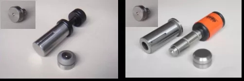
Integral punches or cores suitable for multiple plate thicknesses
The counterbore forming die is directly made by grinding the tip of the punch of the standard round upper die into a counterbore. It can be applied to a certain range of counterbore processing with different plate thicknesses.
However, since the punch core has to limit the plate thickness, once the punching stroke is excessive, the punch and the lower die may be damaged or even break the punch. Therefore, it can only be applied to some high-precision CNC punching machines or countersinking of specific sizes.
Several Methods of Determining the Size of Counterbore
In our technical communication with many customers, we found that many customers still have some deviations in understanding the size of the simple forming of the counterbore.
The main reason is due to the following three processes and methods for determining the size of counterbore holes we summarized below. Due to the different methods, the shape after the processing is completed and the original needs of the customer are deviated.
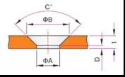
The customer directly clarified the dimensions of the counterbore, and requested that the counterbore be made in strict accordance with the indicated size. For any manufacturer, this approach does not require redundant communication, which is indeed the most convenient and trouble-free.
The products usually processed by this kind of customers are sheet metal products of Japanese or European and American customers (such requirements are also common for domestic Huawei and Taiwan customers). In this case, the dimensions of ΦB and ΦA will be strictly required, and the maximum dimensional tolerance will be required. Within +0.2. However, because the size is completely limited, the customer may mechanically implement the requirements of the upstream customer, and sometimes it may not match the matching screw.
The customer gave each size of the counterbore, but did not indicate whether the size can meet the needs in the end; this situation is the most thankless situation for our mold design engineers.
Although the customer has given the size, but because he does not know whether the size is possible (or does not understand the customer’s requirements), often after the countersink is made, the size of the processed countersink can not be put in or the screws can not be put in the final actual assembly. If it is higher than the board, or if it is deemed unqualified by the customer, a size modification will be required. This leads to a waste of human and financial resources on both sides of the supply and demand (of course it is a waste of delivery time).
Therefore, in this case, we generally recommend that customers adopt the third method to ensure the size of the countersink.

The customer provides countersunk head screws or countersunk pull (rivet) nails for assembly after counterboring processing, and it is clear that as long as the countersunk head can be put in and not higher than the plane of the plate.
For our company, this method only needs to draw the size of the screw (or rivet) head first, and then draw the counterbore size according to the size of the screw head, and provide it to the customer for confirmation. Although it is a little troublesome, it can be confirmed in advance. Complete and efficient communication can greatly reduce the subsequent revision of the cutter head size.
※In addition to the commonly used national standard sizes, countersunk head screws or pull rivets also use many non-standard sizes. Therefore, if the customer is not clear about the specifications of screws or pull studs, it is recommended to use the third size method to determine the size of the counterbore.
Use of countersink forming die
01
Login graphics of the mold
Counterbore forming is generally a special mold. Therefore, in the programming software of any brand of thick tower CNC punch press, it is generally necessary to register the shape of the salad mold.
In order to facilitate the identification of the tool in the tool arrangement diagram, the shape can be drawn as the figure shown on the left as a special two-dimensional tool figure for the salad mold. The A and B dimensions are the A and B diameters of the salad, and the “bowl” in the center is the cross-sectional shape of the salad, representing the upward and downward forming directions, respectively.
02
Size selection of pre-punched holes
Before using a new counterbore cutter head, the size of the pre-punched hole must be accurately determined. For the same pre-punched hole, depending on the material and thickness of the plate, the size of the salad can be processed. There are some subtle differences. We can first determine the size of the first pre-punched hole according to the following figure;
In the figure, use two vertical lines to connect the large diameter B of the salad to the upper and lower planes of the plate thickness, and then use a horizontal line to connect the midpoint of the two vertical lines (that is, half of the plate thickness). At this time, the horizontal line and the salad section The two oblique lines and the two vertical lines of the major diameter will be divided into the a-area triangles as shown in the figure, and the upper and lower a-area triangles on each side have the same area size. In this way, the D size is actually the approximate size of the pre-punched hole. We can imagine that the actual salad extrusion is the process of squeezing the material from one triangle b to another triangle a.
If expressed by a formula, it can be calculated according to the following formula
D=t/2*tan(C/2)*2+A
The size of the pre-punched hole calculated by the above formula is not necessarily a completely accurate trial processing value. First, use a punch similar to this size to test the punch, check the size and diameter of the extruded counterbore, and then increase or Reduce the size of the pre-punched hole and try punching again until the size meets the requirements.
03
Mold installation
1. Before the mold is loaded into the turret, the height of the mold needs to be measured in the first row, as shown in the right picture:
(1) If the mold is installed on a hydraulic or servo press that can adjust the stamping stroke through parameters, the length of the entire upper mold can be directly measured. Generally, the entire length of the upper mold should be less than 207.5mm.
(2) If the mold is installed on a mechanical punch that cannot adjust the stamping stroke, please remove the guide sleeve first and measure the length of the upper mold. Generally, the entire length of the upper die should be less than or equal to 203mm. If it is not measured in this way, it may be that the length of the punch is too long, and the mold will be broken during the first test;
(3) Since the lower mold is flat, the height of the lower mold is generally between 30-30.2mm.
2. Clean the inner and outer sliding surfaces of the mold, and fill the guide sleeve with lubricating oil. If it is a replaceable counterbore tool bit or a replaceable punch-type counterbore upper die, pay attention to check the stop (locking) screw of the tool bit to avoid accidental loss of the tool bit during use!
3. First install the lower mold on the lower mold base of the turret, and knock the lower mold with a copper rod to make the lower mold completely flat.
4. Install the upper mold in the upper mold station hole of the turret, and press the upper mold with your hands at the same time to see if the upper mold can slide up and down in the work station smoothly.
04
Mold debugging
The debugging process of counterbore forming dies is the same as the debugging method of general special forming dies. Therefore, please refer to the forming operation manual of the relevant equipment or the information provided by the mold manufacturer for the detailed method. However, please pay attention to the following methods during debugging:
1. No matter what kind of CNC punching machine, it is strictly forbidden to empty the mold!
2. The counterbore mold must be punched and pre-punched first, and then the counterbore forming is performed;
3. The debugging of the mechanical punching machine must start with the shortest length of the upper die. After the first trial stamping, see if there is a punching shape, and then increase the height of the upper die a little bit until the forming size meets the requirements.
4. The debugging of hydraulic or opportunistic CNC punching machine generally does not need to adjust the physical height of the upper die, but only needs to adjust the punching depth little by little through the forming parameters, until the forming size meets the requirements. (Be sure to fill in the height of the upper and lower molds measured in the previous step in the forming parameter table)

