Custom Metal Fabrication
August 14, 2024Tolerances and Fits in Precision Metal Fabrication
Introduction to Tolerance Systems in Manufacturing
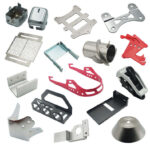
 MetalFabricationChina is a professional metal fabrication manufacturer in China that specializes in high-precision components requiring exact tolerance specifications. In mechanical engineering and manufacturing, the system of tolerances and fits forms the foundation for interchangeable parts and reliable assembly. This comprehensive guide explores all aspects of tolerance regulations as outlined in Chinese industrial standards, providing metal fabricators with essential knowledge for quality production.
Standard Tolerance System Fundamentals
Tolerance Grade Classification
The International Tolerance (IT) grading system establishes 20 distinct precision levels:
-
Ultra-precision grades:
-
IT01 (most precise)
-
IT0
-
IT1
-
-
Standard precision grades:
-
IT2 through IT18 (least precise)
-
The numerical designation indicates the tolerance magnitude, with smaller numbers representing tighter tolerances. When combined with fundamental deviation codes, the “IT” prefix is omitted (e.g., h7 instead of ITh7).
Detailed Tolerance Values by Size Range
The complete matrix of standard tolerance values (Table 1-45) reveals how tolerances scale with part size:
| Size Range (mm) | IT01 (μm) | IT0 (μm) | IT1 (μm) | … | IT6 (μm) | IT7 (μm) | IT8 (μm) | … | IT18 (mm) |
|---|---|---|---|---|---|---|---|---|---|
| 0-3 | 0.3 | 0.5 | 0.8 | … | 6 | 10 | 14 | … | 1.4 |
| 3-6 | 0.4 | 0.6 | 1.0 | … | 8 | 12 | 18 | … | 1.8 |
| … | … | … | … | … | … | … | … | … | … |
| 400-500 | 4.0 | 6.0 | 8.0 | … | 40 | 63 | 97 | … | 9.7 |
Key observations:
-
Tolerance values increase exponentially with size
-
Lower grades (IT01-IT4) maintain sub-micron precision
-
Upper grades (IT15-IT18) reach millimeter-scale tolerances
Practical Applications of Tolerance Grades
Grade Selection Guidelines
MetalFabricationChina carefully selects tolerance grades based on component function and manufacturing feasibility:
| Tolerance Grade | Typical Applications |
|---|---|
| IT01-IT1 | Master gauge blocks, reference standards |
| IT1-IT4 | Precision gauges, calibration equipment |
| IT2-IT5 | Aerospace components, precision bearings |
| IT5-IT7 | Engine parts, hydraulic components |
| IT5-IT12 | General mechanical fits |
| IT8-IT14 | Raw material stock allowances |
| IT12-IT18 | Non-critical dimensions, structural elements |
Manufacturing Methods by Tolerance Requirement
Achieving required tolerances demands specific processing techniques:
| Tolerance Grade | Recommended Manufacturing Processes |
|---|---|
| IT01-IT1 | Fine lapping, superfinishing |
| IT1-IT5 | Precision grinding, honing |
| IT3-IT6 | Rough lapping |
| IT4-IT6 | Final lapping |
| IT5-IT7 | Diamond turning, cylindrical grinding |
| IT6-IT8 | Precision milling, fine boring |
| IT7-IT10 | CNC turning, powder metallurgy |
| IT10-IT12 | Conventional turning/planing |
| IT12-IT15 | Drilling, punching |
| IT15-IT18 | Casting, forging |
Fundamental Deviation System
Alphabetical Designation System
The tolerance position system uses 28 fundamental deviation codes:
-
Hole designations: A, B, C, CD, D, E, EF, F, FG, G, H, J, JS, K, M, N, P, R, S, T, U, V, X, Y, Z, ZA, ZB, ZC
-
Shaft designations: a, b, c, cd, d, e, ef, f, fg, g, h, j, js, k, m, n, p, r, s, t, u, v, x, y, z, za, zb, zc
Special cases:
-
H = basic hole
-
h = basic shaft
-
JS/js = symmetrical deviation (±IT/2)
Deviation Notation Standards
Consistent symbols facilitate international understanding:
| Component | Upper Deviation | Lower Deviation |
|---|---|---|
| Hole | ES | EI |
| Shaft | es | ei |
Calculating Limit Deviations
Hole Deviation Calculations
For holes A-H:
-
Fundamental deviation = Lower deviation (EI)
-
Upper deviation (ES) = EI + IT
For holes J-ZC:
-
Fundamental deviation = Upper deviation (ES)
-
Lower deviation (EI) = ES – IT
Shaft Deviation Calculations
For shafts a-h:
-
Fundamental deviation = Upper deviation (es)
-
Lower deviation (ei) = es – IT
For shafts j-zc:
-
Fundamental deviation = Lower deviation (ei)
-
Upper deviation (es) = ei + IT
Tolerance Zone Designation Examples
MetalFabricationChina uses standardized notation for clarity:
Hole Examples:
-
Diameter 50mm, H8 tolerance:
-
φ50H8
-
φ50⁺⁰·⁰³⁹
-
φ50H8(⁺⁰·⁰³⁹)
-
Shaft Examples:
-
Diameter 50mm, f7 tolerance:
-
φ50f7
-
φ50⁻⁰·⁰²⁵₋₀.₀₅₀
-
φ50f7(⁻⁰·⁰²⁵₋₀.₀₅₀)
-
Fit Systems and Selection
Base System Alternatives
-
Hole-Basis System (Preferred)
-
Constant hole tolerance (H)
-
Varying shaft tolerances
-
Advantages: Reduced tooling costs, simpler inspection
-
-
Shaft-Basis System
-
Constant shaft tolerance (h)
-
Varying hole tolerances
-
Applications: Cold-rolled shafts, precision ground rods
-
Fit Classification System
| Fit Type | Hole-Basis Range | Shaft-Basis Range | Characteristics |
|---|---|---|---|
| Clearance | A-H | a-h | Always positive clearance |
| Transition | J-N | j-n | Potential clearance/interference |
| Interference | P-ZC | p-zc | Always negative clearance |
General Tolerance Standards (GB/T 1804-2000)
Linear Dimension Tolerances
MetalFabricationChina applies these when dimensions lack specific tolerances:
| Tolerance Class | 0.5-3mm | 3-6mm | 6-30mm | 30-120mm | 120-400mm | 400-1000mm | 1000-2000mm | 2000-4000mm |
|---|---|---|---|---|---|---|---|---|
| Fine (f) | ±0.05 | ±0.05 | ±0.1 | ±0.15 | ±0.2 | ±0.3 | ±0.5 | ±0.5 |
| Medium (m) | ±0.1 | ±0.1 | ±0.2 | ±0.3 | ±0.5 | ±0.8 | ±1.2 | ±2.0 |
| Coarse (c) | ±0.2 | ±0.3 | ±0.5 | ±0.8 | ±1.2 | ±2.0 | ±3.0 | ±4.0 |
| Very Coarse (v) | ±0.5 | ±1.0 | ±1.5 | ±1.5 | ±2.5 | ±4.0 | ±6.0 | ±8.0 |
Angular Tolerances
Critical for alignment and assembly:
| Tolerance Class | ≤10mm | >10-80mm | >80-120mm | >120-400mm | >400mm |
|---|---|---|---|---|---|
| Fine (f) | ±1° | ±30′ | ±20′ | ±10′ | ±5′ |
| Medium (m) | ±1°30′ | ±1° | ±30′ | ±15′ | ±10′ |
| Coarse (c) | ±3° | ±2° | ±1° | ±30′ | ±20′ |
Preferred Tolerance Zones
Shaft Tolerance Zones
116 total options including:
-
59 commonly used zones
-
13 preferred zones (highlighted)
Preferred examples:
-
h7 (most common)
-
g6 (precision running)
-
f7 (general rotation)
-
e8 (large clearance)
Hole Tolerance Zones
105 total options including:
-
44 commonly used zones
-
13 preferred zones (highlighted)
Preferred examples:
-
H7 (standard hole)
-
G6 (precision location)
-
F7 (sliding fits)
-
E8 (large clearance)
Practical Fit Applications
Hole-Basis Preferred Fits
MetalFabricationChina’s most frequently specified fits:
| Fit Designation | Clearance/Interference | Typical Applications |
|---|---|---|
| H11/c11 | Very large clearance | Loose pulleys, agricultural equipment |
| H9/d9 | Large clearance | Free-rotating parts, high temperature |
| H8/f7 | Moderate clearance | Bearings, gears, normal rotation |
| H7/g6 | Minimal clearance | Precision slides, measuring instruments |
| H7/h6 | Zero clearance | Locating surfaces, alignment |
| H7/k6 | Transition | Gear hubs, coupling fits |
| H7/n6 | Light interference | Permanent assemblies, bearing seats |
| H7/p6 | Medium interference | Press fits, high-stress connections |
| H7/s6 | Heavy interference | Shaft collars, permanent mounts |
Shaft-Basis Equivalent Fits
Mirror images of hole-basis system:
-
C11/h11
-
D9/h9
-
F8/h7
-
G7/h6
-
etc.
Advanced Fit Characteristics
Clearance Fit Details
| Designation | Characteristics | Applications |
|---|---|---|
| a,b | Extreme clearance | Rare, special applications |
| c | Very large clearance | Loose machinery, thermal expansion |
| d | Free rotation | Conveyors, agricultural equipment |
| e | Visible clearance | Long spans, multiple supports |
| f | Smooth rotation | General machinery, pumps |
| g | Precision slide | Measuring equipment, valves |
| h | Neutral location | General positioning, alignment |
Transition/Interference Details
| Designation | Characteristics | Assembly Method |
|---|---|---|
| js | Balanced clearance | Hand pressure |
| k | Near-zero clearance | Light tapping |
| m | Slight interference | Rubber mallet |
| n | Moderate interference | Press fitting |
| p | Light press | Hydraulic press |
| s | Heavy press | Thermal methods |
Manufacturing Implementation at MetalFabricationChina
As a professional metal fabrication manufacturer in China, we implement these tolerance principles through:
-
Design Phase:
-
Critical dimension identification
-
Proper tolerance specification
-
Fit selection based on function
-
-
Production Control:
-
Process capability matching
-
Tooling selection by tolerance
-
In-process inspection
-
-
Quality Assurance:
-
Statistical process control
-
First article inspection
-
Final verification
-
-
Documentation:
-
Complete tolerance documentation
-
Inspection records
-
Certification packages
-
Conclusion
This comprehensive guide to tolerance systems provides MetalFabricationChina with the technical foundation for producing precision components that meet global standards. By mastering these fundamental regulations, we ensure proper part functionality, interchangeability, and quality across all manufacturing applications. The detailed tables and specifications contained herein serve as essential references for engineers, designers, and quality professionals in the metal fabrication industry.
Our expertise in applying these tolerance principles enables MetalFabricationChina to deliver superior quality components for industries including automotive, aerospace, energy, and precision machinery. We continuously refine our processes to maintain leadership as China’s premier metal fabrication specialist.